![]() David Hannaford's robot pages.
David Hannaford's robot pages.
Speed measurement using an encoder disk
The simplest means of measuring speed is with an encoder disk mounted either on the motor shaft or on the wheels. A sample encoder disk that you can size for your own use is included here. Copy it into wordpad or a similar program and size it to whatever size you need.
 |
The encoder disk will be illuminated by an LED and the reflected light picked up by a phototransistor with a narrow viewing angles (if necessary shielded within a small black tune so that it only sees one sector at a time). The disk shown has 44 black and white sectors so will generate 44 pulses each time the disk turns round once. If the wheels are more than about 4cms in diameter it is probably easiest to glue a paper encoder disk onto the wheels as seen in this picture. The red and blue leads next to the motor go to the LED and phototransistor which in this case are infrared ones. | 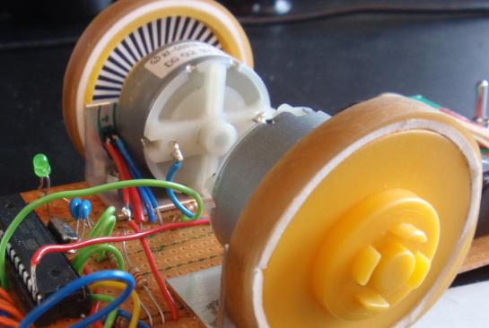 |
Make sure that the LED and phototransistor are close to each other and a few millimeters away from the encoder disk. In this example we have drilled two 3mm holes above each other in the angle bracket that also holds the motor in place. The LED and phototransistor are pushed through these two holes and are held in place adequately by the stiffness of their leads back to the stripboard.
With a 5cm diameter wheel as seen in the picture above and an encoder disk with 44 segments the positional accuracy that we can detect from each stripe will be 50mm x Pi (3.14) divided by 44, i.e about 3.5 mm. If we write the code in the microcontroller so that it detects the start and the end of each black or white segment then we get double this accuracy or about 1.8mm. So if we are using the pulses to measure distance covered we can do so to a couple of millimeters.
If we are measuring speed and have a target speed of say 2 wheel revolutions per second (i.e. 30 cm per second) then we should see the start or end of a segment roughly every 5.7 miliseconds (1000 / 2 x 2 x no of encoder sectors). If we see them in a shorter time we are going too fast and so should reduce the PWM mark space ratio to slow the motor down. If it takes longer than this then we are going too slow and so should speed up the motor by increasing the PWM mark space ratio. When coding this, do not forget to put in some code that says that if it takes more than say 5 times the target speed time we may have a stopped wheel and will never see the next pulse, so when we reach this time we should speed up the wheel.
 |
If the wheels are small and there is not enough room for this encoder disk on them, or you want to put an encoder on the motor shaft or on a separate wheel, you can salvage some very useful small encoder disks with slots in them from old computer mice that have the rubber ball in the bottom of them. There will be 2 encoder disks in each mouse, one for detecting each direction of movement. This picture shows a typical one found in many PC mice. It is plastic and has a shaft running through the middle of it . You will also find a small infrared LED and phototransistor with it, but you may or may not be able to use these. |
 |
As well as mounting the PC mouse
encoder disks onto the motor shaft or wheels you can also
use them as trailing wheels as long as the surface you
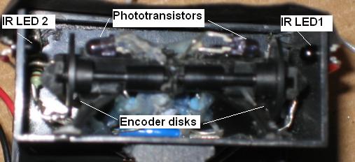
will be going over is smooth. In this picture the two PC mouse encoder wheels have been left on their original shafts and mounted inside a black plastic enclosure with an IR LED at each end and two phototransistors collecting the light coming through the encoder slits. |
The circuits for the IR LED and the phototransistor will be exactly the same as for the line following sensors.
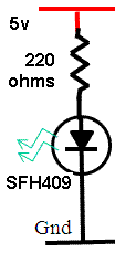 |
For the Infrared transmitter, if
we have a 5 volt supply and use an SFH409 infrared LED
that we want to run at 20 milliamps we will drop 1.3
volts across the LED, leaving 3.7 volts across the series
resistor. Using ohms law this means using a series
resistor of 185 ohms or in practical terms the nearest
standard value which is 220 ohms. A good match spectrum wise for the SFH409 IR transmitter LED is the SFH309 phototransistor. The transmitted wavelength (950 angstroms) is close to that which the SFH309 phototansistor is most sensitive to and they both have a reasonably narrow transmitting and viewing angle. A series resitor of 10K ohms will limit the current through the device to about half a milliamp and give a reasonable variation between seeing the white and black stripes. The variation will probably not be enough to directly drive a logic signal so should be read by an analogue to digital converter input on the microcontroller, and a pulse counted every time the voltage increases or decreases above the average value. |
The signal that comes from the phototransistor will not be a simple on off signal but will almost certainly follow a sine wave shape. If you are really clever you can detect where on the sine wave shape the signal actually is and get an extra level of positional accuracy. This technique if used can give at least a factor of 10 improvement in positional accuracy, but is not necessary for the line following project that we are describing.
Using a hall effect device
If we want to use magnetism instead of light to tell us our speed we can mount a very small circular magnet onto the motor shaft. A motor that has a shaft coming out of both ends is useful for this as we can attach the magnet to one end and put the hall effect chip by that, and take the drive to the wheels from the other end of the motor.
A hall effect chip will produce a sine wave signal as the north and then the south poles of the magnet pass across it. This can be fed into our microcontroller to measure the pulse times in exactly the same way as for our phototransistor output.