![]() David Hannaford's robot pages. -
How to build a line follower
David Hannaford's robot pages. -
How to build a line follower
This section tells you all about the things that you need to know to let you decide what type of line follower you want to build and what the components are that you might decide to use. There are plenty of design choices, so not every line follower will look or behave the same way.
At the end of this section there are links to pages with practical examples of how to make the various parts of a line follower that are described below. I have tried to assume minimal electronics knowledge, so skip over the bits that you already know and use Wikipedia to find out more about the things that aren't clear from my descriptions.
What it needs to do
A line follower needs to be able to travel along a flat surface and as a minimum must be able to follow a line drawn on the surface.
Some line following competitions use a white line (such as 19mm white insulating tape) on a black background, whilst others use a black line (perhaps drawn with a black board marker or marked out with tape) on a white paper background.
In addition, the line follower may need to stop when additional marks are seen offset from the line. There may also be marks that indicate when corners start or finish, which can be used to help control the speed of the line follower.
The line that is being followed may cross itself, but this will normally be done at right angles. There will also usually be a constraint on how tight the turns will be, as defined by a minimum radius.
The aim is to follow the line from the start to the finish area in the shortest time.
What components will be needed
You may also decide to have these items, but they are not essential for the simlpest designs:
Options
There are lots of design options, which may be influenced by what parts you have available and whether you want to compete in specific organised events or just against your friends. Below we will look at the main options that are available for each area of the design.
Drive systems
The first thing to decide is how to arrange the motor drive and steering
The main choices are to either use two similar motors, with one on each side driving and steering like a tank, or to use one motor for providing drive and one for steering, such as the layout used in most radio control model cars.
| If we go for one motor on each
side we just need 2 wheels - like this This is often also called a wheelchair drive layout |
 |
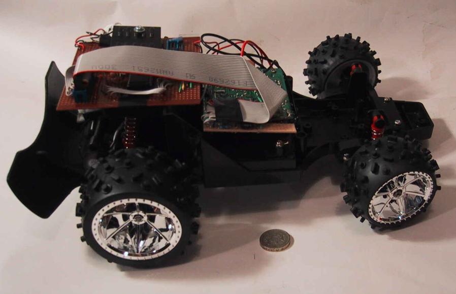
If we use one motor for drive
and one for steering we will probably need 4 wheels -
like this. But we could get away with 3 if we just use one wheel at the front or back. |
 |
Next we need to think about how the motors will connect to the wheels.
At the simplest, for the wheelchair layout the wheels can be just pushed onto the motor shaft. In practice the motor shaft may be a different size to the hole in the centre of the wheel so some form of sleeving will be used to match the sizes.
| Most small electric motors are designed to run at speeds around 6000 rpm so if the motor is connected directly to the wheel as above we will get a high top speed, but relatively poor acceleration & deceleration. We may therefore want to incorporate some gearing of between 3:1 and 10:1 to give better control. Here we see a white pinion gear with 12 teeth pushed onto the 2mm motor shaft engaging with a green 46 tooth gear that is on the same axle shaft as the wheel. This gives a gear ratio of 3.8 to 1. | 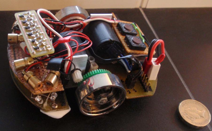 |
| If we are using conventional rear wheel drive car layout and the motor is smaller than the wheel then it is possible to mount it alongside the axle joining the two rear wheels. Here, in this detail from a Scalextric slot car the pinion on the motor shaft has 11 teeth and engages with a gear with 36 teeth fixed onto the rear axle, providing a gear ratio of 3.27:1 | 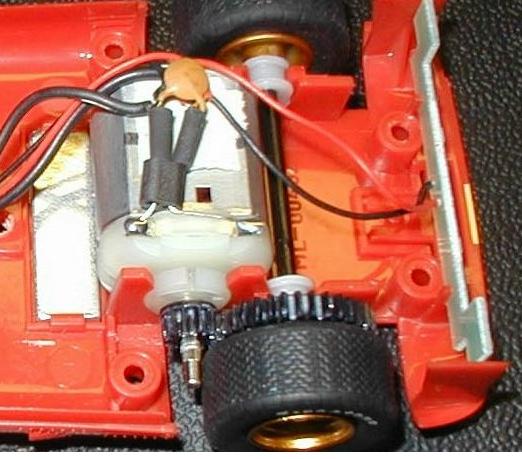 |
Where the motor is larger, or for ease of mounting, we may mount the motor with its shaft facing to the rear. In this case we need either a crown and pinion gear or a worm gear to turn the drive through 90 degrees as it drives the rear axle. | 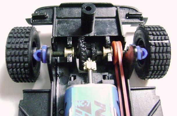 |
All of the motors illustrated above are small DC motors with brushes - the most common and cheapest form. It is possible to use brushless motors or stepper motors but these will be more complex to control so for now we will ignore these.
Sensors
Now we need to think about how we are going to detect the line that we trying to follow, and also detect any extra markers on the track indicating the start and end of turns, or the start and end of the course. The line and markers may be black against a white background, or more normally for UK competitions a white line on a black background.
There are 5 main options for detecting the line:
With all of these detectors we are likely to want to also illuminate the line or markers to cope with situations where the ambient light is poor or variable. We can use Light Emiiting Diodes (LEDs) to illuminate the line and markers with either visible light or infra-red light.
So many choices - let's whittle them down a bit by looking at their complexity and practicality.
LDRs are relatively slow to react to changes in light, so if we want to be able to follow the lne at a decent speed we will avoid using these.
Cameras and vision systems are also slow (typically around 30 frames per second) as well as being complex and expensive, so we can probably rule these out as well unless you want a challenging project.
Bar code readers and linear optical arrays can be used but are not very fast and are more complex than we need for this project, so unless you really want to play with these devices that leaves us with photodiodes and phototransistors.
A photodiode generates a current dependent upon the amount of light it sees, whereas a phototransistor amplifies this current, so produces a more easily detected change between seeing black and white, so you may as well use a phototransistor rather than a photodiode as they are no more complex and not significantly more expensive.
If we use a phototransistor that is only sensitive to infrared light and illuminate the track with infrared light we don't need to worry too much about variations in the natural ambient light which could make it harder to detect the line or markers. The only problem with doing this is that you can't see the infrared light so it is harder to see if it is working. The alternative is to use white or red light illumination and phototransistors that react to natural light.
Whatever sort of light we use we will need a source of illumination such as a Light Emiiting Diode (LED) and a photodiode or photo-transistor to detect it at each point where we want to de able to detect the line or marker. Normally we will have at two or four pairs of LEDs and phototransistors - Two in the centre to detect the left and right edges of the line we are following, and opionally one on the left and one or the right at the relevant distance from the centre to detect markers if they exist.
We want these sensors to detect the line and marker as soon as possible so they are usually mounted pointing downwards at the front of the vehicle.
 |
This line follower just has two
red light LEDs and phototransistors pointing downwards in
the "nose" It has had a plug added that switches it between following a white line and a black one. |
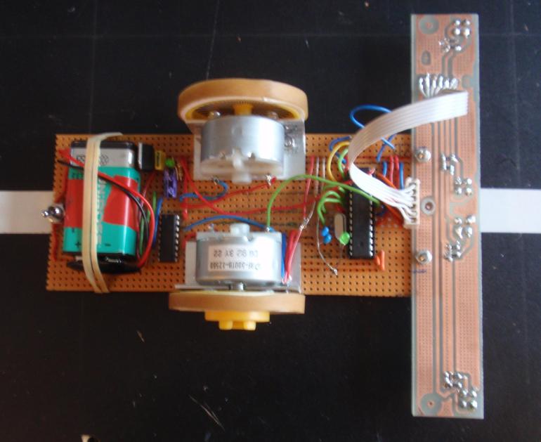
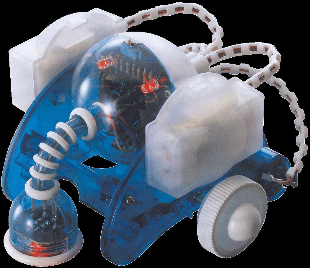
|
This line follower has 4 infrared LEDs and phototransistors pointing downwards in the bar across the front. It has two in the centre and one at each end of the bar. The bar also helps to shield the sensors from the ambient light. |
The positioning and spacing of the sensors will depend on the width of the line being followed and how far away from the line any markers will be. A UK competition line is typically 19mm wide (the same width as standard electrical insulation tape) and markers extend from 40mm either side of the line for 80 mm. So to detect the middle of the side marks the side sensors need to be placed about 80mm out from the centre.
Processing logic
The processing circuits and the logic within them are what makes it a line follower. As a minimum it needs to be able to detect whether the line sensors are seeing black or white and turn the line follower left or right. This will be done either by turning the steering if it is a conventionally steered vehicle, or by speeding up or slowing down the motors on one side if we are using the wheelchair or tank drive layout.
Here is the some of the logic that we may want to implement - assuming we are following a white line on a black background
This will be OK as long as we get back on the line as soon as we start to drift off it, but does not work if we come off the line and so see black with both line sensors, so we might want to add this extra logicfor when both central sensors are seeing blacck:
This is exactly the logic that is implemented in "Nosey" the blue and white line follower shown in the sensors section above, and it works very well for a fixed speed line follower.
However, if we want to be able to stop at the end of the course or go faster on the straights we also need some extra logic to detect the markers and take account of them accordingly.
In standard UK competitions the course start and stop markers are on one side of the line and the corner start and end markers are on the other side of the line, so we might want to add some logic that says:
This is not quite as straightforward as it sounds as we will see the white marker many times as we cross it, so we only want to make the speed change as we detect a change from black to white (at the start of the marker) or on a change from white to black (at the end of the marker).
Electronic circuits
Once again we have plenty of choices, depending on what level of skill we have in constructing circuits and whether we want to implement the logic in hardware or software.
As a minimum we will need :
We may also want:
OK let's look at each of these areas in turn, starting with the simplest
The power source
The battery needs to have a high enough voltage to drive the electronics and enough power and capacity to drive the motors. - The electronics typically run at either 3.3 or 5 volts but onlyrequire a small current if using standard logic circuits or a microprocessor. The motors may require up to an amp at 3 to 12 volts depending on the power of the motors. If these two requirements are sufficently different we might even use 2 separate batteries. If you choose motors that will run from 3 or 6 volts then one battery will usually be fine.
The motors will drain a battery quite quickly, so it is useful if rechargeable batteries are used, as although they are dearer, you only need to buy them once.
Either four AA or AAA batteries in series giving 6 volts or a PP3 battery giving a nominal 9 volts are common choices, but note that the rechargeable versions of these have a slightly lower nominal voltage (1.2 volts per cell instead of 1.5volts), so four rechargeable AA batteries are likely to be deliver nearer to 5 volts and a rechargeable PP3 nearer to 8.2 volts.
Normal batteries and the motors are quite heavy so you only want them to be just big enough for the job, otherwise you are carrying a lot of unneeded weight around, which will slow you down and make it harder to get round the corners, so don't just go for the biggest of everything.
If you have plenty of money available then rechargeable Lithium Polymer (LiPo) batteries can deliver high currents and have very low weight so can be attractive, but require special chargers and a lot of care in use. Incorrect charging can cause them to catch fire or explode, and running them down to flat will also destroy them, so they are only recommended for more experienced users. Cell voltage for a LiPo battery is nominally 3.7 volts so we would often use a 2 cell battery giving a nominal 7.4 volts.
A charged battery will deliver higher than nominal voltage initially, then as it runs down it will deliver below nominal voltage, so choose the batteries to allow for the circuits to still work when the batteries are at least 20 percent below the nominal voltage, and for a PP3 battery even down to 33 percent below (i.e. 6 volts instead of the nominal 9 volts).
 |
You need some connectors appropriate to the type of battery used, and possibly something to hold the batteries, particularly if using four AA or AAA batteries in series. A spring loaded case like this one shown is ideal. It one holds two batteries at the front and another two behind, and connects them all in series giving 6 volts at the two poutput leads. |  |
You also need a switch in the battery lead to power it up when needed. I also like to put in an LED with a series resitor across the battery after the on/off switch to show when the power is on and to indicate when the battery is running down.
Voltage regulation
Because of these issues of changing battery voltage we often put in a voltage regulator to provide a steady voltage to the more critical electronic circuits, but usually drive the motors from the full battery voltage
A typical voltage regulator is a three pin device with an input, a ground and an output connection. We normally need to put a tantalum or electrolytic capacitor across the input and ground, and also across the output to ground to make it work correctly as shown in the circuit diagram below. Both these types of capacitors will fail if put the wrong way round so loook for a plus or minus on them to get the correct orientation.
 |
Voltage reguators can be fixed or variable, and normal or low dropout. A fixed voltage regulator takes a variable voltage that is higher than the required one on its input pin and delivers a predefined voltage on its output pin, in our case we probably want 5 volts or 3.3 volts for the electronics. A variable regulator allows us to use a pair of resistors across two of the regulator connections to select the output voltage. Either way there needs to be some difference between the input and output voltages. For a normal regulator this is about 1.2 volts. i.e. if we want 5 volts out we need to put at least 6.2 volts in. A low dropout regulator will have a lower difference between the input and output - perhaps as low as half a volt. So if we are using a 6 volt battery and want to drive 5 volt electronics we had better use a low drop out regulator, but if we using a 9 volt PP3 battery we are OK with a standard regulator. |  |
Line Illumination and Sensors
We are almost certainly going to illuminate the line and markers with some LEDs. As mentioned earlier they may produce visible light (e.g. red, white, blue, yellow or green) or infra red "light" which is invisible to us.
 Some common 3mm and 5mm LEDs |
LEDS can be various sizes, but we will probably use standard 3mm or 5mm diameter ones. Unlike filament bulbs they only work one way round. These sizes of LEDs always have a flat on one side and one lead shorter than the other. This flat side and short lead usually indicates the negative side - i.e. the lead that goes to ground in the circuit shown. But do check your specific LEDs as a few are the other way round. Our circuit shows 2 LEDS in parallel, each with a resistor to limit the current flowing through them. Too much current and they burn out. We will normally want between 10 and 20 milliamps going through the LED, so depending on the supply voltage (3.3, 5 or 9volts) and the amount of voltage dropped across the LED (typically between 1.5 and 3 volts) we wil need resistors R1 and R2 to be a few hundred ohms. You can calculate the precise resistor value as: Supply voltage minus LED voltage drop, multiplied by 1000 and then divided by the required current in milliamps. E.g 5 v supply - 1.5 volts drop across the LED =3.5 volts. Multiply by 1000 to get 3500 and then divide this by the required current of 20 milliamps = 175 ohms for each of R1 and R2. |  |
Phototransistors and photodiode sensors look very similar to LEDs and also come in 3mm and 5mm standard types, so try not to get them mixed up, particularly if thye have a clear body. We will use one phototransistor for each LED, so that the LED shines light down onto the line and we detect the reflection with the phototransistor. The phototransistor conducts current when it detects light and it acts as a high resistance when there is no light. We use a similar circuit to the LEDs to limit the current through the phototransistor and take our output from the junction of the resistor and phototransistor as shown in the circuit below.
Some common phototransistors |
We can treat the phototransistor
as being similar to a variable resitor which has a high
resistance when there is no light seen, and a low
resistance when it detects a reasonable amount of light. Lets assume for example that it has a dark resistance of 50,000 ohms and a light resistance of 500 ohms. We want to choose R1 in our circuit to be between the dark and light values say at 5,000 ohms. Ideally the ratio between the fixed resitor and the dark resistance value of PT1 (in this case 10 to 1) should be similar to the ratio between the light resistenace value of PT1 and the fixed resistor (also 10 to 1 in this case). So how it works is this: When there is no light, PT1 wil be equivalent to 50,000 ohms and the fixed resistor R1 will be at 5000 ohms. The supply voltage will be split across these two resistances in a ratio proportional to their values. So if the supply is 5 volts about half a volt will go across R1 and 4.5volts across PT1. Therefore the voltage on the output wire will be 4.5 volts. When the light is detected and PT1 conducts, its effective resiatnce drops to say 500 ohms. The 5 volt supply will be split across the fixed resitor R1 of 5000 ohms and the phototransistor PT1resistance of 500 ohms. In this case about half a volt will appear across PT1 and 4.5 volts across R1. in this case the voltage seen on the output wire will be around half a volt. So as PT1 sees dark and then light the voltage at the output wire goes from 4.5 volts down to half a volt which gives us a very good change in voltage to work with for the following circuits. |
Implementing the logic
At its simlpest, we need something that when a sensor goes off the line and sees dark (if we are following a white line on black) it causes the line follower to turn to bring it back onto the line. The easiest way with a wheelchair format mose is just to stop or slow down one motor on the relevant side.
We said that when both sensors are seeing white we want both motors going so that we carry on going straight ahead. If the left sensor sees black we have veered to the left, so if we stop or slow down the right motor we will turn to the right. If the right sensor sees black then we have veered to the right and we need to slow down or stop the left motor. So if we use the ouputs of our sensors to slow down or stop the opposite motors we can implement the logic we require.
Controlling the motors
So how do we contol the motors? Well like all the rest of our design we have several choices. For a simple solution we can just use a transistor as a switch to turn the motor on and off, but if we want more control and the ability to reverse the direction of the motor we might use a circuit called an H bridge which can be implemented with individual transistors or using an integrated circuit. We will look at both of these options below.
A simple transistor switch
Let's start by looking at using a transistor as a switch. If we examine the circuit below, we see that it is quite similar to our phototransistor circuit, except that it has the motor where R1 was, and instead of light coming into PT1 has a wire for an input into the transistor T1.
| How does this work? Well, when a
transistor has a current flowing into its input (called
the base) it allows a larger current to flow across the
other two terminals (called the collector and emitter).
So if we put a suitable current into the input, the
transistor will switch on and current will flow from the
positive supply through the motor then through the
transistor from the collector to the emitter and down to
ground, causing the motor to run. And when there is insufficient input to the base of T1, the transistor will switch off and it will look like a large resistor (similar to how PT1 looked when it was dark), which means that most of the supply voltage will appear across T1 and hardly any current will be available to go through the motor, so it will stop. |
 |
So, all we have to do now is to arrange for the output from the sensor to be connected to the input to the transistors that switch the motors and we are in business. Lets see how we do this.
The output from our phototransistor circuit will be a low voltage when it sees the white line, which is when it needs to provide a high input to our motor circuit, so we have a problem. For our logic for a white line follower we want a high voltage when we see a white line. There are a few ways to solve this, but the simplest way is to turn our photoransistor circuit almost upside down.
| Our original circuit is on the
left, and the new one on the right. Now in the new
circuit when PT1 sees light it's effective resistance
goes low and so most of the supply voltage is dropped
across R1, leaving the output wire at a high voltage. And
when PT1 is seeing dark, its resistance goes high and the
output is low. This is now exactly what we need for a white line follower, where a white line generates a high signal which can be used to switch on the motor. However if you had been building a follower for a black line on a white background the original circuit would have been the right way round, so it is useful to know about both. |
 |
So all we need to do now is to connect our sensor and motor switch circuits together. We want the high voltage on the sensor outout to create a high current into the base, and a low voltage to create a low current into the base.
| In this circuit instead of just connecting the output of the phototransistor directly to the base of the motor switch transistor we have added two more resistors. R2 is there to make sure that when the output from PT1 goes close to the supply voltage we don't let too much current flow into the base of T1. If our transistor has a gain of 500 then 2 milliamps into the base will allow 1000 milliamps (i.e.1amp) to flow through the motor. If PT1 output is at 8.5 volts then using ohms law (Resistance = voltge divided by current) then 4250 ohms will provide 2 milliamps at the base of T1 to drive the motors at full speed. In fact there will also be a small voltage drop of 0.6 volts across the base and emitter of T1 so we should really also subtract this from our 8.5 volts giving 7.9 volts before we calculate the resistance R2, which now works out at around 3.9k ohms |  |
R3 is there to make sure that when PT1 is seeing dark we switch off T1 fully. Transistors need about 0.6 volts at the base before they will switch on and we know that when PT1 is seeing dark it will have about 0.5 volts on its output. That is a bit close to our 0.6 volt threshold so if we set R3 at half of R2 i.e. just below 2000 ohms then the 0.5 volts from PT1 output will spread across R2 and R3 in the ratio of 2 to 1(i.e 2 thirds of our 0.5 volts will go across R2 and 1 third across R3) This will bring the voltage at the junction of R2 and R3 to less than 0.2 volts which since this is connected directly to the base of T1 will ensure that it switches off fully. You might get away without using R3 but if it is there the circuit should be a bit more reliable
Connecting up our basic circuit
We now have a circuit that connects a central photosensor to a motor. We need two of these. To implement our logic correctly the left side central sensor needs to be connected to the right side motor, and the right side central sensor connected to the left side motor. Connect up the battery and switch to the +ve and ground lines on this circuit and we have a basic line follower. And in the meantime we have learnt about resistors, transistors, LEDs, photdiodes and have a good idea now how we design circuits in parts and join them up.
Using an H bridge
Ok, so perhaps you also want to look at the other option that we mentioned.
An H bridge is a circuit that not only allows us to switch our motor on and off but also lets us connect the supply to the motor either way round, so that we can make the motor go forward or backwards.
 |
The basic circuit is shown here
and yes it does look H shaped. If inputs 1 and 4 have
current going into them and inputs 2 and 3 don't, then
only transistors T1 and T4 will switch on, and current
will flow from the positive line, through T1 then through
the motor and down through T4 to ground, making the motor
run in one direction. If however only Inputs 2 and 3 have current going into them then only T2 and T3 will switch on and current will flow from the positive line through T3 then through the motor (the other way to previously) then through T2 to ground, making the motor run in the other direction. You may notice that transistors T1 and T3 look slightly different to the ones we have previously seen They are a different type but work in a similar way. Just think of the arrows showing the direction of flow of current in this circuit. |
If T1 and T3 are switced on and T2 and T4 are swtched off then the current can't get down to ground and the motor will stop. However if we switch T1 and T2 on (or T3 and T4) at the same time we will short out the positive line to ground through these transistors and they will overheat and fail, so we need to be careful how we use a simple H bridge. A common way to avoid this problem is to put another transistor in front of inputs 2 and 4 driven from inputs 1 and 3 which inverts the incoming signal. This then says that if input 1 is on then input 2 is automatcally off, and if input 1 is off then input 2 is automatically on. Which means that we can never short out the transistors and we only now need 2 inputs to control the motor direction.
If we don't want the complexity of building our own H bridge circuits there are plenty of integrated circuits availble that provide 2 H bridges in one package and so can drive two motors with just a few control inputs.
Improved processing logic
Of course if we want to make use of this better motor control and perhaps control the speed of the motors as well as the direction we need to be a bit more clever about how we map the phototransistor outputs to the H bridge motor drivers.
Whilst we can build fixed circuits to do this, if we want flexibilty to easily try out different logic we may as well use a microcontroller.
Using a microcontroller
A microcontroller is a computer processor in a single chip. They can be small, with as few as 8 connecting pins, or have over a hundred connections. Many of the pins on the package connect internally to "Ports" which can be used to either accept inputs which can be interrogated, or to drive outputs to make things outside happen - e.g. lighting an LED, providing an input to an H bridge for a motor, or sending a signal to a servo to move an arm or leg.
Logic is written in a programming language on a PC which tells the microcontroller what inputs to look at and when various outputs should be sent out. The logic is "compiled" on the PC which turns it into a form that the microprocessor can understand and then it is "dowloaded" into the microprocessor and stored there so that you can run the program without having to have the PC connected. A development environment is used on the PC to write the program that will go in the microcontroller and a serial or USB cable is used to send the program from the PC to the microcontroller when it is ready.
This may seem complex and expensive but microcontrollers are cheap and many of the development envronments are available for free on the Internet. So as long as you have access to a PC and the Internet then you should not be too worried about the complexity or cost. Some environments have been made particularly easy for beginners to get to grips with and we will use these when we show you some examples of code.
Measuring speed
It is useful to know how fast we are going at any time so that we know whether we could go faster to get a shorter time, or perhaps need to slow down for a corner.
This means typically having something on one or more of the motor shafts or wheels that can generate pulses as the motor and wheel turns. If it is on a wheel it can be on the driven ones or on a separate trailing wheel.
We will normally either use a small magnet mounted on the motor shaft to trigger the generation of the pulses with a Hall effect detector that detects the strength of a magnetic field, or use a pattern of holes or stripes on a wheel that can have light shone through it or reflected off it using an LED and a phototransistor. Either way we can measure either the number of pulses in a fixed time, or the time between one pulse and the next, to get the speed. Processing and using these pulses to improve performance will almost certainly require the use of microprocessor but it is not difficult to do.
Varying motor speed using Pulse Width Modulation (PWM)
Once we know how fast a motor is going we might want to speed it up on slow it down. A motor's speed is dependent upon the current going through it and the load on it. We have seen how we can use a transistor to switch the current on or off to the motor but this basically only gives us two speed values (going or stopped). However if we were to switch the motor on and off in quick succession (let's say a few hundred or thousand times a second) we would get an intermediate value of current and the motor would run at an intermediate speed.
Now if we also vary for each time we switch the motor on and off, the ratio between the "on" time and the "off" time we get what is called pulse width modulation, and the ability to vary the current going through the motor and hence its speed precisely.
 |
On the left, we see that for each pulse it spends most of the time "off" and only a small amount of time "on" so the average current is low, so the motor will run slowly. On the right we see that each pulse spends most of its time "on" so the average current is high, so the motor will run much faster. |  |
To achieve this precise timing of the turning on and off of the motors at the necessary speed we will almost certainly want to use a microcontroller.
So, are you ready to start building?
The following links take you to pages with practical examples of how to actually build many of the things we have been talking about in the sections above.
Have fun !!
Links to practical pages
Using stripboard to build circuits and act as a chassis
Using an H bridge and PWM to control the speed and direction of the motors
Speed measurement with an encoder disk
Using an Arduino processor and development environment
Using a Microchip PIC processor and development environment