Robots I have built:
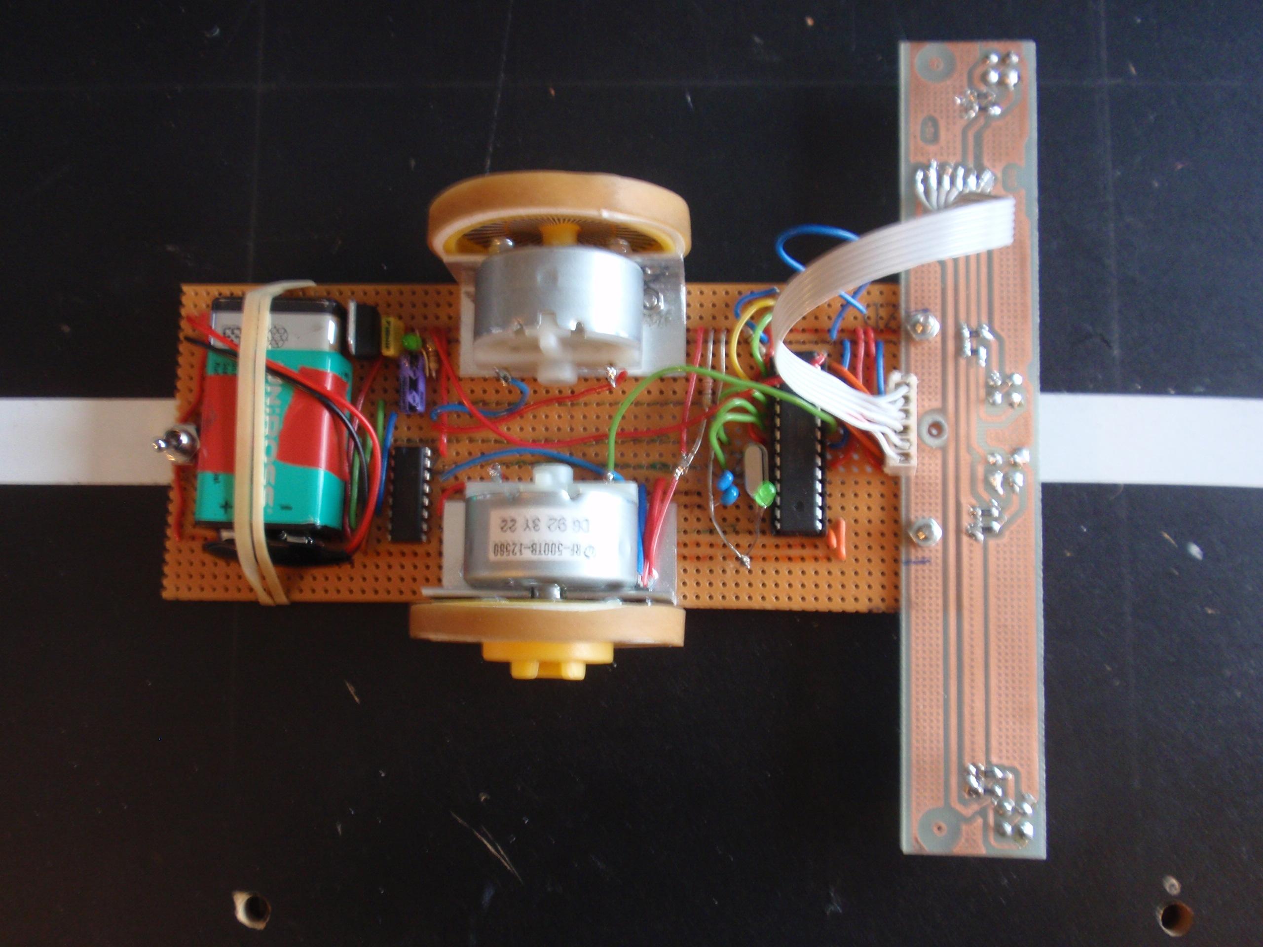
This direct drive line tracker was built to demonstrate how a low cost simple line follower could be built using simple stripboard electronics, an extremely simple drive system and programmed using the Arduino programming environment.
The microprocessor is an Atmel ATMega168 20p with the Arduino bootloader in it, which means that it can be programmed from the open source Arduino development environment just using a serial cable from a PC or a USB to serial converter if the PC does not have serial ports.
The only other chips are a 5 volt regulator.and an L293D H bridge driver that allows the small signals from the Amtel processor to control the larger currents required to drive the motors.
The wheels are connected directly onto the electric motor shafts, with just a piece of sleeving to convert the 2mm motor shaft to the 3mm hole in the wheels. This limits the torque available but means that a relatively high speed can be achieved.
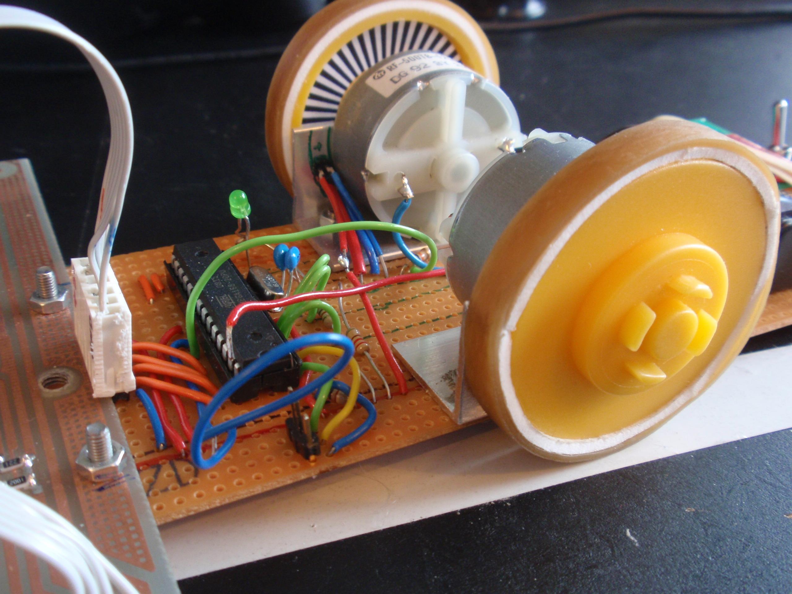
The wheels have a paper pattern glued on the inside (visible on the second picture) which is read by an infrared transmitter and receiver mounted next to the motor, as the wheel turns. This enables the speed to be deduced.
The "hammerhead" at the front contains a further 4 infrared transmitter receiver pairs. Two in the centre are used to detect the edges of the line, and one pair at each end are used to detect marks to the side of the line that indicate the start or end of turns etc.
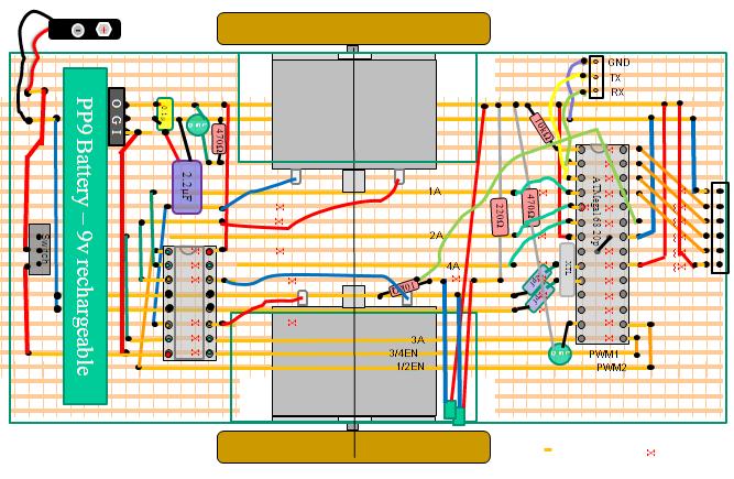
The layout of the stripboard is shown below:
This line follower was subsequently
modified to use a couple of geared motors to give better control.
(see photo below)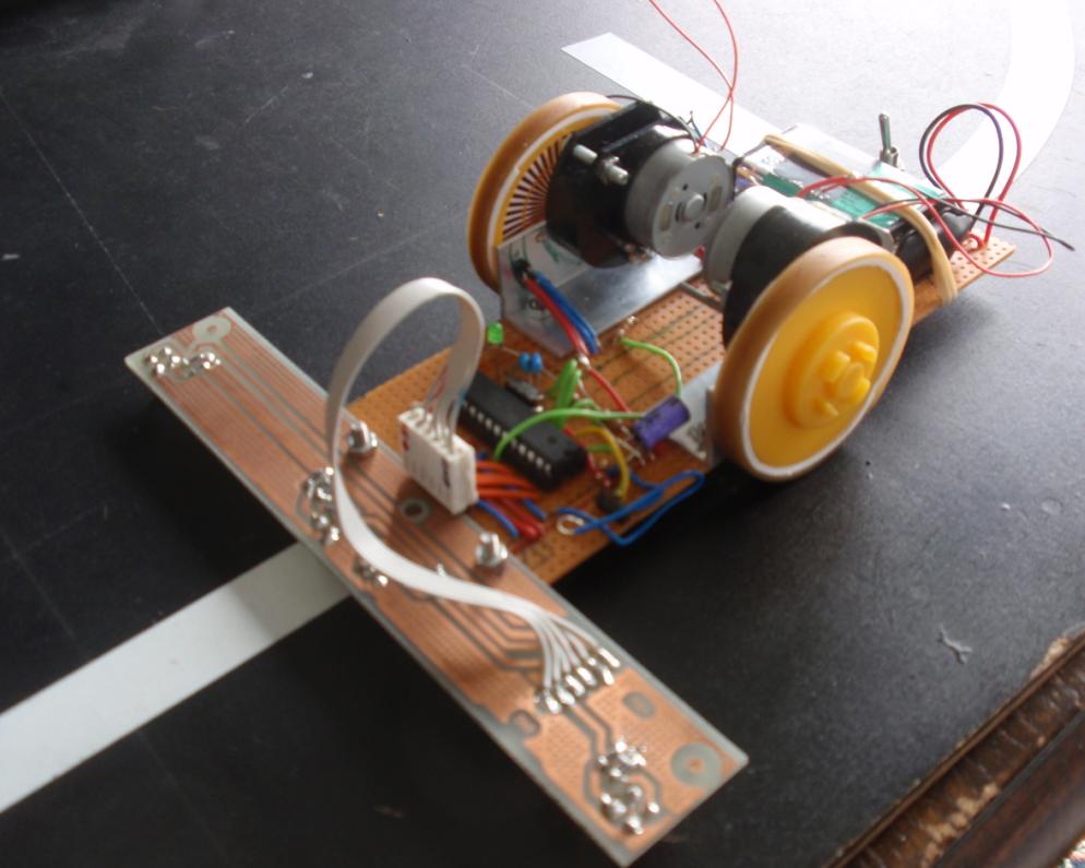
The motors used were Part number 37-0443 from Rapid online( motor 37-0443 details here ) and they bolted straight onto the previous brackets by simply drilling one new mounting hole. The integral gearboxes that come with the motor are set up with a 27:1 ratio (3 gears each giving 3 :1) but can be apparently be disaasembled to provide a 9:1 ratio if you want it to go faster. This extra gearing means that each motor can accelerate and decelerate much better than before, which helps it with speed control and more accurate line following.
While making this change, the aluminium sleeving previously used to convert the 2mm motor gearbox drive to the 3mm hole in the wheels was replaced by 3mm styrene plastic tubing from Raboesch. After inserting a short section of it into the wheel it was and then drilled out to bring the inner diameter up from 1mm to 2mm. This gave a nice tight fit for the wheels with no slipping
Arduino Code
The basic code for this line follower is included here as a text file. To use it, open the Arduino development environment and paste the text into a new sketch, then compile and upload it.
The logic for this code is :
Speed control
Overall speed control is achieved by counting how many times we go round the main loop before the right wheel encoder senses a change from black to white or white to black. It keeps track of the highest and lowest readings that it ever gets from the encoder and uses a value midway between these as the value when we trigger a change of segment being seen.
The number of counts is compared against the desired number to see if we are going too fast or too slow. We then increase or decrease the PWM ratio accordingly to maintain a steady base speed.
Line following
If both middle line sensors are seeing white we are on the line so we apply the base speed (i.e. the PWM ratio) to both motors to go straight ahead.
If one line sensor sees black and one sees white (i.e. we are drifting off the line. The base speed (i.e. the PWM ratio) is modified to speed up one motor and slow down the other (to make it turn back onto the line)
If both line sensors see black we have gone right off the line and we use the lastseen variable (which remembers which side we last saw the white line on) to decide whether to swing left or right to get back onto the line. We turn more sharply than when following along the line as we may need a sharper turn to bring us back onto the line.
Updating the motor speed
When we have calculated the base speed and applied the direction control adjustments to it we look to see if the adjusted speed has changed for each motor. If it has, we send a new PWM ratio to the relevant motor.
There is plenty of scope for adjusting the factors that affect how well it follws a line. You can easily change the desired speed, how the speed control modifies the PWM ratio, how sharply we turn when we go a bit off line, and how much we turn when we go right off the line. All of these will significantly affect the performance.
Additional code
If you want to write some additional code, here are some ideas for areas that you could develop to improve things even further:
.