![]() David Hannaford's robot pages.
David Hannaford's robot pages.
Using stripboard for circuits and as a chassis
If you have access to a soldering iron and are able to do soldering, then stripboard (or veroboard as it is also known) is a very handy way to put a circuit together from individual electronic components.
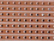 |
Stripboard consists of a sheet of a hard plastic like material with strips of copper on one side and holes in each direction every tenth of an inch. The spacing of the holes is designed to match the spacing of the pins on standard Dual Inline Packaged (DIP) integrated circuits, and the size of the holes means that the leads from components like resistors, capacitors and LEDs can also be easily pushed through from the top side and soldered onto the copper tracks on the bottom side, which then makes the connections between the components. The sheets come in various sizes and can easily be cut using a small hacksaw. |
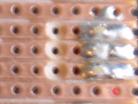 |
Breaks can be made in the copper tracks either using a specialised stripboard track cutter or just as easily with a 3.5mm drill turned by hand pressure. This image shows three connections having been made by soldering in components that are on the other side of the strip board, and then these three tracks being isolated from the rest of the circuit by the copper on the track being cut in three adjacent holes using a 3.5mm drill. |
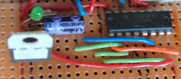 |
This picture of the top side of some stripboard shows a 16 pin integrated circuit and various other components with their leads going through the holes and soldered below. Notice aslo that there are quite a few other single wires which are taking signals or power from one track to another. Often when we make up a circuit on stripboard we can make some of the connections between the components with the copper tracks but frequently need to supplement this with other connections made with these link wires. |
Where an integrated circuit like the one shown is put on the board it is aligned so that one track goes to each pin., i.e. the copper strips are running up and down on the back of the board in this picture. However to make sure that we don't short out the pins on the oppposite sides of the integrated circuit we will need to make breaks in the copper tracks underneath where the integrated circuit is soldered in.
Because stripboard is stiff it can not only hold the electronic components in a robot circuit, but can also be used as a chassis upon which small motors, gears and sensors are mounted. The only things to be careful of are that if you need to drill any holes in the board for bolts etc. be careful as the board can crack around where the holes are in the board. Also if you put a bolt through the board be careful that it is not either breaking a track that you need, or shorting together two or more tracks with the nut or bolt.
The beauty of stripboard is that you can place components into the board without soldering them to see how much space they take up. This is useful as the physical layout of the parts so that they all fit in is almost as important as making them be connected correctly to implement the required circuit.
You can also draw on the top of the board with a felt tip pen which is useful for marking the row of holes that are the connections for the positive supply from the battery, a regulated supply and the ground lines or the positions where components will go.
When laying out a circuit onto stripboard it is normal to start with the powes supply and ground tracks, placing one at one side and the other side, then work across the circuit placing the components so that the copper tracks make the majority of the required connections.
It is very easy to get confused when transferring the positions of the required breaks in the tracks to the side where the break is made, so be very careful about getting this right. Also be sure that when you make a break in the track you go all the way across that track. It is very easy to leave a minute sliver of copper on one edge and not notice it. A watchmakers small eyeglass or other magnifier is really useful to check for this.
Finally, when you solder in the components make sure that the copper side of the board is nice and clean before you solder onto it and that the solder does not bridge across to the adjacent track. Most stripboard circuits will get one or more of these above faults on it as you build it, so close inspection of every joint and every track break after you make them will mean that you can fix these problems before you put power onto the board and perhaps watch something melt !!